EN
EN
 English
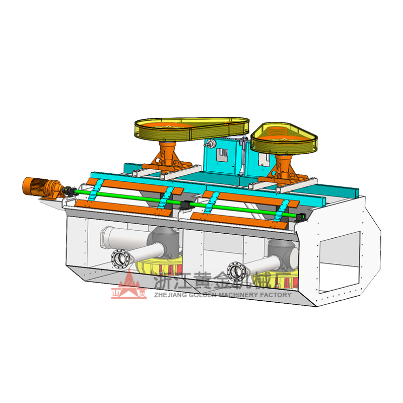
SF-type floater machine is a mechanic mixing floater with double functions of self-absorption of air and slurry. It adopts a forward-leaning tank and double-blade turbine of a new structure, coordinated with fluid duct and the false bottom device. The tank slurry has a double cycle of both above and below in a fixed flow manner, which contributes to the coarse mineral suspension. An SF-type floater is mainly composed of a tank body, main drafts with impellers, a motor, a scraper, and driving equipment. Those with a volume over 10m^3 are set with fluid duct and false bottom.
Working Principle
When the SF flotation machine is working, the motor drives the main shaft through the V-belt to rotate the impeller at the bottom. The main feature of this flotation machine is reflected in the impeller. The impeller has backward-inclined double-sided blades, which can realize the double circulation of the slurry in the tank. When the impeller rotates, the slurry in the upper and lower impeller cavities generates centrifugal force under the action of the upper and lower blades (i.e., the main and auxiliary blades) and is thrown to the surroundings, so that a negative pressure zone is formed in the upper and lower impeller cavities. At the same time, the slurry on the upper part of the cover plate is sucked into the upper impeller cavity through the circulation holes on the cover plate, forming an upper circulation of the slurry. The slurry thrown out of the lower impeller cavity has a higher specific gravity than the three-phase mixture thrown out by the upper blade, so the centrifugal force is larger, the movement speed decays more slowly, and an additional driving force is generated on the three-phase mixture thrown out by the upper blade, so that the centrifugal force increases, thereby increasing the vacuum degree in the upper impeller cavity, playing an auxiliary suction role. When the lower blade throws out the slurry to the surroundings, the lower slurry is replenished to the center, thus forming a lower circulation of the slurry. The air is sucked into the upper impeller cavity through the suction pipe and the center tube, mixed with the sucked slurry, forming a large number of fine bubbles, which are evenly dispersed in the tank after the cover plate stabilizes the flow, forming mineralized bubbles. The mineralized bubbles float to the foam layer and are scraped out by the scraper to form the foam product.
Application
This series of flotation machines is suitable for the selection of non-ferrous and ferrous metals, and can also be used for the selection of non-metals such as coal, fluorite, and talc.
Equipment features
1. Large air intake and low power consumption;
2. Each tank has the triple functions of air intake, slurry suction, and flotation, forming a flotation circuit, without any auxiliary equipment, horizontal configuration, and convenient for process changes;
3. Reasonable slurry circulation can minimize the precipitation of coarse sand;
4. It is equipped with an automatic control device for the slurry surface, which is easy to adjust;
5. The impeller has backward-inclined upper and lower blades. The upper blades generate an upward circulation of the ore pulp, and the lower blades generate a downward circulation of the ore pulp;
6. The SF-type flotation machine and the JJF-type flotation machine can be configured as a combined unit, with the SF type as the suction trough and the JJF type as the direct current trough, and the entire unit is installed horizontally.